- 6. Performances
-
- 6.1 Testing methodology
- 6.2 Sine wave test
- 6.3 Clean chord test
- 6.4 Time envelope test
- 6.5 Ear perception
6. Performances
We have the algorithm, it is coded in C and it can run on the DSP board. Now, we need to test it and see how well it performs.
6.1 Testing methodology
For performance analysis purposes, the C code is modified in order to read input samples from a sound file in wave format and output the result in a new sound file in the same format. These simulations are run on a PC instead of a DSP. The time-domain comparison is performed with a waveform visualizer software such as GoldWave. The frequency-domain comparison is done with Sigview, which allows computing the FFT over a given window of the signal. The waveform and spectrum visualization tests cover the entire range of the pitch shifting factors but focus mainly on the minimum and maximum factors (corresponding to -4 semitones and +4 semitones respectively).
Three criteria are considered to evaluate the performances of the algorithm: the accuracy of the pitch shifting factor, the latency introduced (which should not exceed 50ms), and sound quality (audio artifacts should be limited). The expected latency for a phase vocoder using frames of 1024 samples at a sampling rate of 44000 samples per second is around 30 milliseconds. The phase vocoder usually introduces some artifacts such as phasiness, detuning, tremolo and smearing. Even though the waveform and spectrum provide significant information about the performances, the overall sound quality cannot be quantified. For this reason, qualitative tests based on ear perception are then performed with the DSP board connected to an electric guitar and an amplifier.
6.2 Sine wave test
The first step is done with an input vector made of a sine wave with a fundamental frequency of 1000Hz. The results are shown in figures 6.1, 6.2 and 6.3. The maximum latency is 30 milliseconds, which falls into the acceptable region. There is no phasiness as there is no phase discontinuity. This validates the efficiency of the phase adjustment done by the phase vocoder. Moreover, there is no tremolo as the amplitude of the sine wave remains constant over time, except at the beginning due to the Hanning window. The FFT is performed on each signal over a frame of 10 milliseconds during steady-state. The magnitude of each spectrum is computed and results are shown in figures 6.4, 6.5 and 6.6. For comparison purposes, the magnitude of each spectrum is normalized.

Figure 6.1: Input sine wave

Figure 6.2: Sine wave with a pitch shift of four semitones down

Figure 6.3: Sine wave with a pitch shift of four semitones up

Figure 6.4: Spectrum of the input sine wave

Figure 6.5: Spectrum of the sine wave with a pitch shift of four semitones down

Figure 6.6: Spectrum of the sine wave with a pitch shift of four semitones up
When the sine wave is shifted by four semitones down, the expected fundamental frequency is given by equation 6.1.

Equation 6.1: Expected frequency for a sine wave of 1000 Hz with a pitch shift of four semitones down
The measured fundamental frequency from figure 6.5 is equal to 790 Hz, which is close to the expected fundamental frequency. When the sine wave is shifted by four semitones down, the expected fundamental frequency is given by equation 6.2.

Equation 6.2: Expected frequency for a sine wave of 1000 Hz with a pitch shift of four semitones up
The measured fundamental frequency from figure 6.5 is equal to 1260 Hz, which is close to the expected fundamental frequency.
6.3 Clean chord test
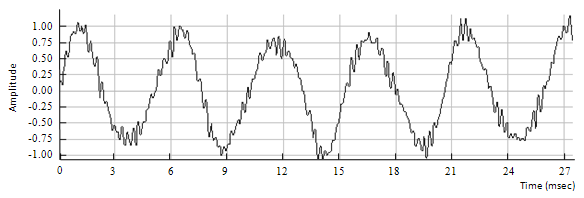
The signal in figure 6.7 is a 27 milliseconds frame of a chord, which is the superposition of several notes played at the same time on different strings of the guitar. This is referred to as a clean chord since there little distortion on the signal. This implies that there should be few overtones or frequency components apart from the harmonics. The results are shown in figures 6.8 and 6.9.

Figure 6.7: Input clean chord

Figure 6.8: Clean chord with a pitch shift of four semitones down

Figure 6.9: Clean chord with a pitch shift of four semitones up
The FFT of each of the previous signals is shown in figures 6.10, 6.11 and 6.12.

Figure 6.10: Spectrum of the input clean chord

Figure 6.11: Spectrum of the clean chord with a pitch shift of four semitones down

Figure 6.12: Spectrum of the clean chord with a pitch shift of four semitones up
On the previous spectra, the frequency scaling is easily observed for the highest harmonics. This test validates both the ability of the algorithm to shift multiple frequency components appropriately and its ability to preserve the spectral envelope.
6.4 Time envelope test
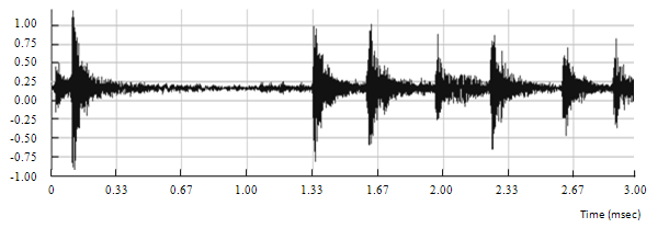
A drum track is used in order to estimate the effect of smearing with the phase vocoder. As a matter of fact, guitar notes played with a sharp attack may be affected by smearing. A drum hit is ideal to estimate the rise time, duration and decay time of a sharp note. This is shown in figures 6.13, 6.14 and 6.15.

Figure 6.13: Input drum signal

Figure 6.14: Input drum signal

Figure 6.15: Input drum signal
The previous figures clearly show that there is no significant smearing introduced by the phase vocoder.
6.5 Ear perception
The system is then tested in real-time with an electric guitar and an amplifier. The results are very good as the timbre of the guitar is well-preserved and the latency is small enough so that the musician stays synchronized when playing.
And that's it! That works! Any suggestions or comments? Just email me: webmaster@guitarpitchshifter.com
Moreover, many people have ask for a Matlab code to test this algorithm. You can find it in the next section.
|
Previous: Software |
Next: Matlab code |
Copyright © 2009- François Grondin. All Rights Reserved.