- 4. Hardware
-
- 4.1 Codec (TLV320AIC23B)
- 4.2 Digital Signal Processor (TMS320C6713)
- 4.3 PC
4. Hardware
So now that we have an algorithm that works and has been tested with Matlab, we need to implement this in real-time on a digital signal processor (DSP) board. We will first look at what we need to run our software that will be written in C.
We used a DSP starter kit from Spectrum Digital to implement this design. Starter kits, even though they are more expensive, will save you a lot of time in hardware debugging because everything has been done for you. This way you can focus on the software. The DSP starter kit we used is the DSP Starter Kit (DSK) for the TMS320C6713 by Spectrum Digital. This DSK comes with the hardware and a license to use Code Composer Studio, which allows you to code and program your chip.
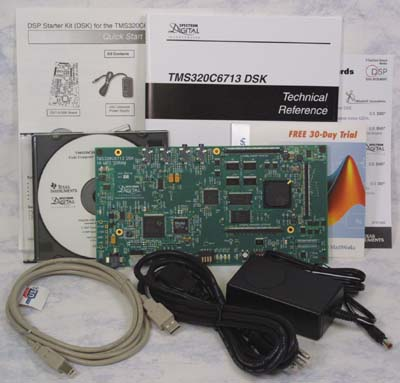
Figure 4.1: DSK starter kit for the TMS320C6713 (Photo courtesy of Spectrum Digital, Inc.)
Two components from Texas Instrument on this DSP Starter Kit are mainly used: the DSP chip (TMS320C6713) and the codec (TLV320AIC23B). The DSP chip performs digital processing, which is the analysis, processing, and synthesis stages in addition to the resampling process. The codec performs data conversion from analog to digital and vice-versa. The starter kit has two inputs (mic in and line in) and two outputs (headphone and line out). The electric guitar is connected in the line in and the line out is connected to the amplifier. The starter kit is connected to a PC via USB and this is used to load the program on the chip and to provide a user interface while the program is running.
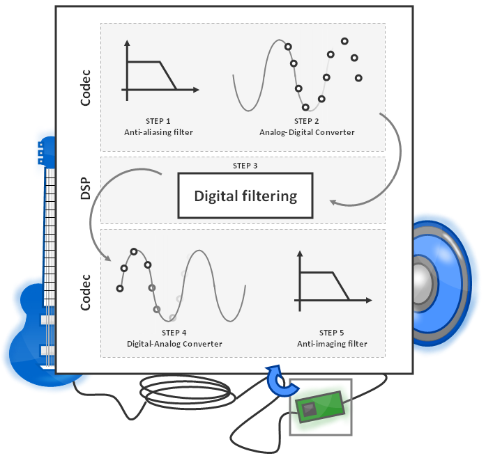
Figure 4.2: Digital Processing Overview
4.1 Codec (TLV320AIC23B)
- Name: TLV320AIC23B
- Manufacturer: Texas Instrument
- Sampling rate: 44000 samples/second
- Word length: 16 bits
A stereo audio codec from Texas Instrument is used in this design. The codec is cool because it manages all input and output issues. You donĺt have to worry about anything and there is a driver with C-callable functions that allow communication between the DSP and the codec.
The TLV320AIC23B is configurable to run at different sampling rates and word lengths. For the purpose of this project, the codec is configured to sample at 44000 samples per second with 16-bit word length. The codec can deal with stereo signals but we will use it for mono signals. This reduces the computation requirements by two and provides the same sound quality for our application.
The analog-to-digital conversion is accomplished with an anti-aliasing filter cascaded with an analog-to-digital converter (ADC). The antialiasing filter is a low pass filter, which is usually a combination of an analog filter and a sharp digital filter. The codec first oversamples the analog signal at a given rate, which is 250 times faster than the sampling frequency of the ADC. The oversampling at such a high rate allows the use of an analog anti-aliasing filter with a large cut of frequency (e.g. 125 times the sampling frequency). The oversampled signal then goes through a sharp digital filter with a cut of frequency of half the actual sampling frequency.
The input power levels of the ADC should be kept in the dynamic range of the ADC in order to avoid any signal distortion. The codec is configured with 16-bit word length, which implies the input amplitude range is divided in 65536 (216) discrete steps.
On the other hand, the digital-to-analog conversion is achieved by use of a DAC followed by an anti-imaging filter. A 16-bit word is sent to the DAC, which also implies that the output amplitude is divided in 65536 (216) discrete points. This is converted to an analog signal and then filtered by the anti-imaging filter in order to smooth the signal.
A software volume controller limits the amplitude of the output signal in order to keep the latter within the dynamic range of DAC to avoid distortion.
4.2 Digital Signal Processor (TMS320C6713)
- Name: TMS320C6713
- Manufacturer: Texas Instrument
- Clock: 225 MHz
- MFLOPS: 1350
- MIPS: 1800
- Program cache: 4KB
- Data cache: 4KB
- Unified cache: Up to 64KB
- Mapped RAM: Between 192KB and 256KB
A floating point DSP chip is used for this design. This chip is clocked at 225MHz and is capable of performing 1350 million floating-point instructions per second (MIPS) and 1800 million instructions per second (MFLOPS). This chip communicates with the codec through multi-channel buffer serial port. This chip is made of eight independent functional units: two fixed-point arithmetic logic units, four fixed-point and floating-point arithmetic logic units and two fixed-point and floating-point multipliers. Pipelining is therefore used in order to improve performances. It has a memory of 4Kbyte direct-mapped program cache, 4K-Byte 2-way data cache, 64K-Byte unified cache or mapped RAM, and 192K-Byte of mapped RAM. The architecture allows some memory extension but this is not required for this application since the algorithm does not require excessive memory space.
4.3 PC
We also used a PC with Windows XP. We need it to program the DSP (the DSK connects via USB) but also to change the parameters of our pitch shifter while it is running. These paremeters are the number of semitones and the volume. Code Composer Studio has its own GEL interface that allows you to change the value of some variables dynamically while the program is running. We could also have designed our own interface with press buttons and a LCD. However, remember this was a school project: we did not have enough time to build a complex interface.
|
Previous: Algorithm |
Next: Software |
Copyright © 2009- François Grondin. All Rights Reserved.